Options for Designing Chilled Water Pumping Schemes
The system for delivering chilled water to end users has changed significantly since the introduction of central chilled water plants. Drivers of this change have included increased cooling demands, improvements in technology and requirements for more energy efficiency.
This blog will examine how chilled water pumping schemes have evolved and discuss the pros and cons of the most common methods employed today.
Direct-Primary Scheme
Initially, chilled water delivery was through a simple direct-primary, constant pumping flow (CPF) scheme. Using this method, chilled water is delivered to the end user at a constant flow rate, independent of the actual load. During part load conditions, control valves at the building coils allow some of the water to bypass the coil, varying the chilled water return temperature. This method of control adjusts the plant output to match the load, but it results in significant waste of energy, doesn’t match flow to building load and results in Low Delta T.
Low Delta T occurs when bypassed chiller water mixes with return water from the cooling coil producing lower chilled water return temperature to the plant. The lower return water temperature reduces the temperature differential (Delta T or ΔT) across the chiller, thus decreasing the overall performance and efficiency of the entire system.
Primary-Secondary Scheme
Recognizing a need to increase the allowable system design temperature differential, in the 1950s engineers devised what is now known as the primary-secondary pumping scheme. This scheme divides the chiller water system into two distinct loops, primary and secondary, hydraulically separated by a neutral bridge. Using staged pumps, this method allows variable flow through the system to match cooling load, while maintaining constant flow through the chillers.
An important decision to make when designing a primary-secondary system is whether to use manifold or dedicated primary pumps. The manifold design allows any pump to apply to any chiller. It’s possible, however, to over pump a chiller, in which case, the plant can fail. Using dedicated pumps is usually a simpler approach and it also means the scheme can handle unequal sized chillers. During the design phase remember that while some pressure drop is good, keep it to a minimum and, lastly, design for 15-25 FPS based on chiller evaporation flow.
The benefits to applying the primary-secondary pumping system are that it’s well understood by existing facility personnel, delivers constant flow through the evaporator, uses simplified controls, features a divided hydraulic head and provides the ability to match flow to load.
On the negative side, Low ΔT is still possible and in fact can become worse during off peak times, when the neutral bridge can be over pumped. Because it calls for more piping, controls and pumps, this scheme is more expensive to set up than a simple direct-primary method. Furthermore, operating and energy costs can be high and more space is required in the plant for the additional pumps and related drives.
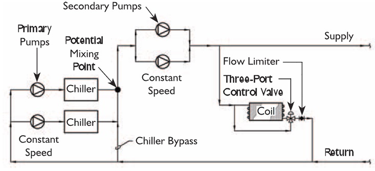
FIGURE 1: PRIMARY-SECONDARY OVERVIEW
Variable-Primary Scheme
Advances in controls and chiller and pump technologies have led to the creation of the variable-primary pumping method. This technique features staged pumps and chillers, relies on variable speed secondary pumps and uses two-way valves.
A major benefit of this method is that Low ΔT can be managed by controlling the pump flow rate and neither a neutral bridge nor three-way valves are required. Using the variable speed pumps, chiller flow is adjustable to match system ΔT and the number of operating pumps does not need to match the number of chillers. Because there are fewer pumps needed with this method, the capital investment is less, energy costs are lower and less plant space is required.
The variable-primary design requires the installation of a minimum flow bypass line in order to avoid low flow tripping. A headered pump design is preferred as well, so the starting of an additional chiller can be slowly increased. A check valve is not recommended, since chillers are brought on in stages before being fully loaded.
The major drawback to the variable primary-pumping method is that because it’s a recent technology there is a lack of familiarity with it in the field. Complex controls are required for chiller staging and unloading and to manage the low flow bypass, so often more training is necessary for staff to be able to operate the system. Finally, the divided hydraulic head used in this scheme increases system design pressure and pump size.
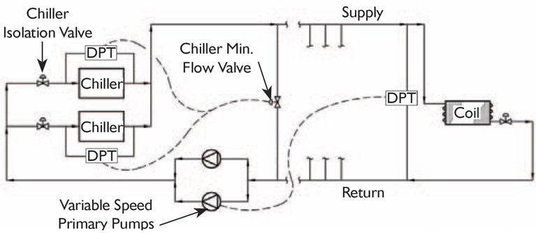
FIGURE 2: VARIABLE-PRIMARY OVERVIEW
Understanding the main chilled water pumping methods enables you to make the best choice for each project, based on the client’s requirements, budget and the skill level of the facility operations team. Figure 3 provides an easy comparison of the three methods to illustrate the benefits and drawbacks of each.
D/P (CPF) Pump Energy: (Base Case) Delta-T Mitigation: Does Not Apply Valve Type: Three-way Installed Cost: (Base Case) Control Complexity: Simple Plant Space: (Base Case)
P/S Pump Energy: 50 - 60% Less Delta-T Mitigation: Higher Energy Valve Type: Three-way Installed Cost: 10% Higher Control Complexity: Simple Plant Space: Larger
V/P Pump Energy: 60 - 75% Less Delta-T Mitigation: Less Energy Valve Type: Two-way Installed Cost: 5% Higher Control Complexity: Can be Complex Plant Space: Same as Base Case